Mononoke Mask · Volume 1
Printing the Mononoke Mask
Four PETG parts, one 210 mm bed, and supports kept off every surface you can see
1.1 The model
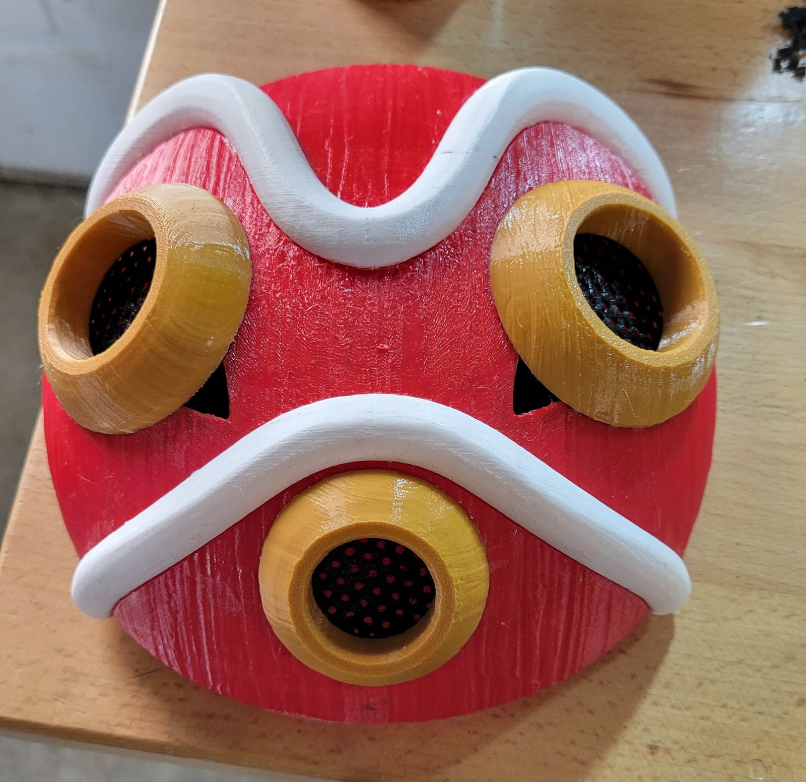
San’s mask from Princess Mononoke is a red dome with two white bands across it, gold rings round the eyes and mouth, and dark lenses inside the rings. The model I printed is “Princess Mononoke Mask with Accessory Pack” by UnchainedHobbies, a free design on MakerWorld made for its mask contest. The designer sized it for a 24-inch head circumference and ships it two ways: as one all-in-one mask for single-colour printing or painting, and split into parts for printing each colour separately. The accessory pack adds a dagger, earrings, chain links and ears.
I printed the split version as four files, one per colour:
Table 1 — I printed the split version as four files, one per colour
| Part | Objects | Largest piece at 82 % | Volume | Approx. weight |
|---|---|---|---|---|
| Mask body (red) | 1 | 185.2 × 198.8 × 75.4 mm | 110 cm³ | 140 g |
| Details (white) | 2 | 178.4 × 94.7 × 52.1 mm | 54 cm³ | 68 g |
| Eye and mouth rings (gold) | 3 | 63.9 × 64.5 × 18.1 mm | 57 cm³ | 72 g |
| Lenses (black) | 3 | 64.6 × 75.8 × 11.7 mm | 6.7 cm³ | 8 g |
The weights are for the parts alone. Supports add a good deal on the mask body and the white details.
The model files themselves stay with their designer. This page covers what I did with them.
1.2 Scale and material
My printer is a Prusa MK3S+, with a 250 × 210 mm bed. The mask body is the part that sets the limit. At 82 % it is 198.8 mm deep, which leaves 11 mm of the bed’s 210 mm to spare. At 87 % it would be 211 mm and would not fit at all. So 82 % is the ceiling, and every other part has to match it.
I set all four files to 82 %. When I started, the mask body was already at 82 % but the other three were still at 75 %. One trap here: PrusaSlicer’s scale field is an absolute percentage of the original model, so a part at 75 % goes to 82 by typing 82, not 109.
I printed all four parts in PETG. My first plan was red PLA for the body, but with the same plastic throughout the whole assembly can be solvent welded. A dichloromethane (DCM) cement softens both faces of a joint and fuses them into one piece, where glue would leave a layer of adhesive between them. These parts are close to solid at their wall thickness, and that is where solvent welding beats epoxy.
1.3 Orientation: protect the face you see
The usual way to judge an orientation is by total support volume. On this mask that gives the wrong answer. I scored every part on a sharper measure: how much support lands on the surface that will be seen. I measured each part’s geometry with my orientation-analysis script and compared each part as the designer laid it out against the same part flipped.
Support on the show face, part by part:
Table 2 — Support on the show face, part by part
| Part | Support on the show face, as laid out | If flipped |
|---|---|---|
| Mask body | 1.8 cm² | 221.3 cm² |
| White detail 1 | 0.7 cm² | 19.1 cm² |
| White detail 2 | 0.4 cm² | 24.9 cm² |
| Black lenses | 0 cm² | all of it |
Flipping the mask body or the white details roughly halves total support, which looks tempting in the slicer’s estimate. It also moves every support contact onto the visible face. None of the four parts was re-oriented. The original orientations were already right.
The only geometry change was on the small black lens. It sat 1.97° off flat, so it hovered 0.2–1.0 mm above the bed and the slicer would have built a useless mat of support under it. Levelled, it prints flat on the bed with no supports at all.
1.4 The mask body
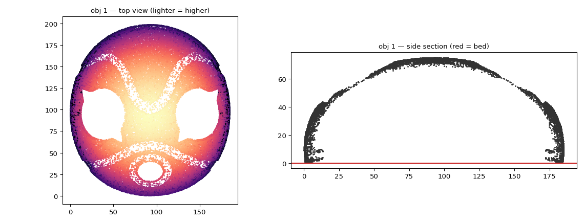
The body is a dome with 2.3 mm walls, 75 mm tall, printed crown up with the rim on the bed. The entire inside is overhang, and nothing changes that, but none of it is ever seen.
It had two real problems.
It stands on almost nothing. The rim is wavy, not flat, so on the first layer the body touches the bed in only 22 mm², split into three islands. On a part 185 mm across, that is a part waiting to lift a few hours in. I ran a tilt scan of ±3° in both axes: the best any rotation managed was 48 mm², so rotation is not the fix. A brim is. Here the brim is capped at 4 mm, because the part already sits 4.7 mm from the front edge of the bed.
The support forest was far too dense. The project came with an organic-support branch distance of 1 mm. Across 225 cm² of overhang in a cavity 70 mm deep, that is an enormous number of branches: slow, heavy and no stronger for it. I changed it to 3 mm spacing with 2.5 mm branches, which gives fewer, sturdier trunks, the right shape for a tall forest. I also lowered the overhang threshold from 50° to 45°. That removes 54 cm² of support contact, because the 45–55° band prints fine unsupported on a well-cooled MK3S+, and on this part all of it is inside anyway.
Mask-body overhang area by angle:
Table 3 — Mask-body overhang area by angle
| Overhang steeper than… | 20° | 30° | 40° | 45° | 55° |
|---|---|---|---|---|---|
| Area | 60 cm² | 100 cm² | 148 cm² | 171 cm² | 225 cm² |
The cost of staying in PETG shows up here. With about 170 cm² of PETG support pressed against a PETG part inside the dome, this is by far the biggest support-removal job in the set, and PETG bonds to itself much harder than PLA does. Since none of that surface is ever seen, I biased the body entirely toward easy release and set its contact Z distance to 0.25 mm instead of the 0.2 mm I used elsewhere. The inside comes out rougher, and nobody looks inside a mask.
1.5 The white details
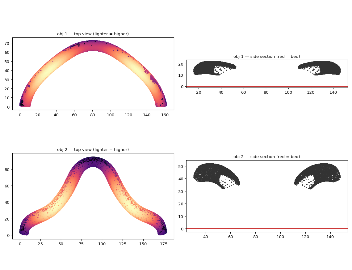
The white details are two solid curved bands about 7–8 mm thick, 162 mm and 178 mm long at 82 %. They arch through three dimensions to follow the mask’s curve, so they print standing on their tips. These were the riskiest prints in the set: bed contact of 0.19 cm² and 0.09 cm², the worst of any part, and the taller one stands 52 mm high on what amounts to two points. I gave them an 8 mm brim and spread them 20 mm apart so their brims would not merge.
A prototype of the white details came out with a few burnt black specks on the top surfaces. Scraping one tells you which kind it is. If it lifts off, the nozzle is dropping cooked ooze as it travels. If it is embedded in the plastic, carbonised material is coming out of the hot end.
The project had avoid crossing perimeters switched off, so the nozzle drove straight across the top of both bands every time it hopped between them. At 240 °C, and with PETG’s habit of drooling, that is exactly where a cooked bead gets wiped off. I turned it on, raised Z-hop from 0.4 to 0.6 mm, set retract-before-wipe to 60 %, and dropped the nozzle to 235 °C. Printing the two bands on separate plates removes the risky travel entirely, and that is how I printed them.
If the specks are embedded instead, there are two usual suspects. One is dark filament left in the hot end, since PETG clears slowly. A long purge or a cold pull before a white print fixes that. The other, the classic MK3S version of this symptom, is a slightly loose nozzle. Plastic creeps up past the heatbreak, bakes onto the heater block, and eventually a flake drops onto the print. The cure is to heat to 280 °C, tighten the nozzle against the heatbreak while hot, clean the block, and fit the silicone sock.
1.6 The gold rings
The three gold rings are shaped like trumpet bells, printed narrow end down. The project had supports switched off, and that was the right call. It is the one genuinely close decision in the set.
The outer bell is the show surface. Because it flares outward as it rises, it is technically an overhang all the way up, but most of it is steep enough not to matter.
Outer-bell area by overhang angle:
Table 4 — Outer-bell area by overhang angle
| Outer bell steeper than… | 25° | 30° | 40° | 45° | 55° |
|---|---|---|---|---|---|
| Area (large ring) | 0.5 cm² | 1.5 cm² | 5.0 cm² | 7.2 cm² | 13.5 cm² |
81 % of the bell is at 40° or steeper and prints cleanly. Only a narrow band near the outer rim drops lower, to about 28° at worst, and that band comes out slightly rough. Turning supports on would trade that small rough band for support scars across the whole visible bell. Flipping the part would protect the bell but leave a knife-edge rim of 0.17 cm² that needs a brim on a visible edge, plus supports inside the funnel, which also shows. Both cures are worse than the disease. The 0.15 mm layer height helps here: at the worst angle it cuts how far each layer steps out from 59 % of an extrusion width to 44 %. The rings touch the bed over 3.5 cm², so they need no brim.
1.7 The black lenses
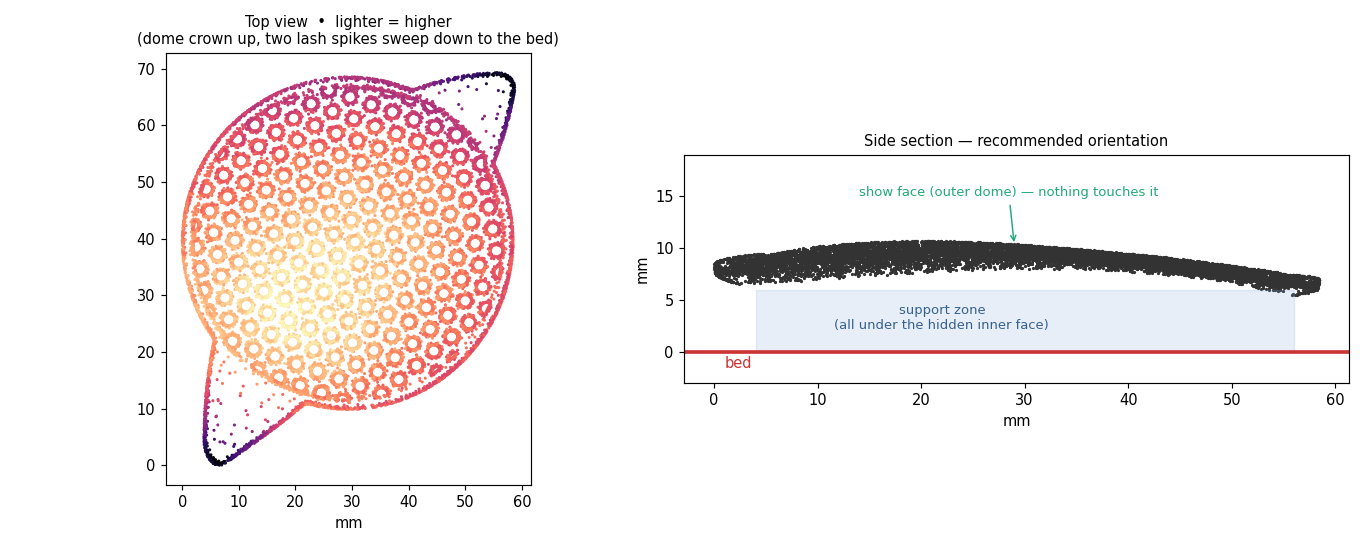
The two large lenses are shallow perforated domes: a 0.95 mm shell with 191 holes 2.3 mm across and webs only about 2 mm wide between them. Anything welded to that takes a web with it when it comes off. They print domed face up, with full support under the concave back that ends up inside the mask. The cap is so shallow that every flat orientation makes one whole face a near-horizontal overhang. Tilting only moves the problem, so the gains all come from the support settings:
- Interface spacing 0.35 mm instead of 0.2 mm. At 0.2 mm the interface is a solid welded sheet against a 1 mm web, and this is the single biggest fix for removal damage.
- XY separation 80 % keeps support out of the 2.3 mm holes.
- 5 mm brim, because the part touches the bed only at about 2 mm² of lash tip.
- Overhang threshold 55°, which trims stray support on the rim.
Support removal is where these parts are won or lost. The method: let the part go fully cold, snip the organic branches near their tips so the forest falls away, then peel the interface sheet from the rim inward, low and flat, in one motion. Pulling straight up puts tension on every hole edge.
1.8 Settings shared by every part
Table 5 — Settings shared by every part
| Setting | Value | Why |
|---|---|---|
| Layer height | 0.15 mm | Cleaner overhangs and hole edges; the one change that helps all four parts |
| Support style | Organic, build plate only | Branches snap off instead of levering against the part |
| Interface pattern spacing | 0.35 mm | The biggest lever on support-removal damage |
| XY separation | 80 % | Keeps support out of holes and off vertical faces |
| Contact Z distance | 0.2 mm (0.25 mm on the mask body) | PETG welds to PETG; raise it if removal fights |
| Interface layers | 2 top / 0 bottom | Peels away as a sheet |
| Don’t support bridges | On | |
| Fan | 40 / 55 %, bridges 60 % | A firmer first layer over support |
1.9 Print order
I printed the parts in order of risk, cheapest proof first:
- Small black lens — 20 minutes, no supports. It confirms the 0.15 mm layers and clean holes.
- One gold ring — shows how the unsupported flare finishes.
- One large black lens — proves the support settings before committing to the second.
- White details — on separate plates.
- Mask body last — the longest print and the most expensive to lose.
1.10 Solvent welding the assembly
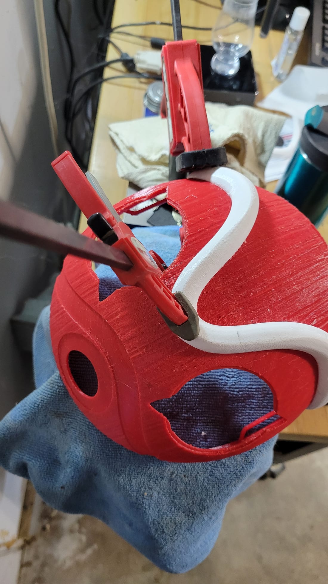
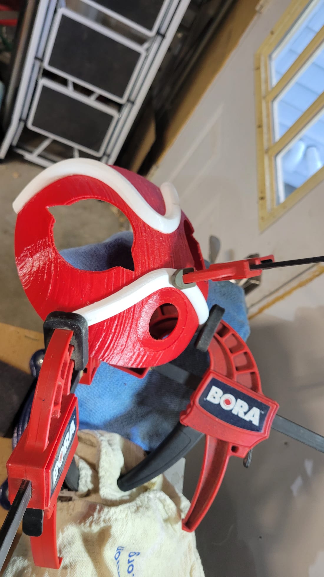
With every part in PETG, I joined the assembly with DCM solvent cement rather than glue, clamping each joint while it set. Work with DCM in a well-ventilated space. Its vapour is the hazard.
1.11 Finishing
The mask was printed, welded and finished on 4 October 2026.
Sources
- UnchainedHobbies, “Princess Mononoke Mask with Accessory Pack,” MakerWorld — https://makerworld.com/en/models/731750-princess-mononoke-mask-with-accessory-pack. The model files are the designer’s, under MakerWorld’s Standard Digital File License, and are not redistributed here.
- All measurements on this page come from my own analysis of the designer’s mesh at 82 % scale, and the settings from my tuned PrusaSlicer projects.
Comments (0)